We had designed a cooking robot not very long ago. The design was prepared as a creative exercise and there are some kinks in it that need to be ironed out. We will list the kinks at the end.
The robot essentially uses a sensor network to perform transfer and heat operations. It can also dip and activate various tools – mixing tools, stirring tools, grinding tools, etc.
Another cool feature of the design is that all tools and operations are driven by a single immovable motor drive.
The cooking robot, if it is realized, should be able to prepare many types of Indian side dishes and cook rice.
One of the things that this robot can’t do is prepare rotis (but there is now an automatic roti maker available in the market that can do that).
In the blog post below, we describe the design of the robot and hereby put it in the public domain.
At the core of the design is the vessel. This is the only part of the design (apart from various tools) which comes into contact with the food.

The vessel has a handle that allows it to be easily ‘picked up’ by the robot, moved around, turned and released.
Various tools, for example, mixing tools, stirring tools, and beating tools can be fitted with similar handles (but with a drive shaft running within to provide a mechanical driving force to the tool tip).
The robot connects with the vessel through a vessel carrier. The vessel carrier is just a square piece. The diagram below shows the vessel carrier in three positions – open, locked and rotated through 45%.
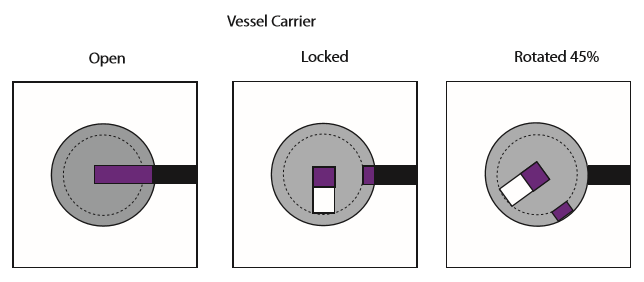
The purple shading denotes the handle of the vessel. There are two concentric rings with slits (shown in grey) in the rectangular carrier.
When the carrier is open, the slits in the slit rings line up and the vessel handle can slide into the carrier.
When the carrier locks, the inner slit ring rotates around the handle shaft, so it cannot slide out of place.
The slits are now at 90 degrees to each other. Whenever they are at 90 degrees with respect to each other, the handle cannot slide out.
If both rings rotate, the vessel rotates with them, as shown in the last of the three figures in the above diagram.
Any number of such vessel carriers can be allowed to run along a set of vertical and horizontal tracks as shown in the following figure.

The tracks are called ‘vessel guides’ because the vessel holders can only run along these guides.
The track and the surface they are cut into form the front face of the cooking robot.
So, in this design, the robot operates entirely in 2 dimensions, in a vertical plane parallel to a kitchen wall. This plane of operation was deliberately chosen to conserve kitchen room, and to allow for pouring operations.
To pour a fluid or mixture from one vessel to another, all that one has to do is position one vessel in a vertical track (N-S) above another vessel running in a horizontal track (E-W) and turn the higher vessel (the pouring vessel). The pouring vessel rises to keep its lower edge at a steady height. The receiving vessel adjusts its position horizontally to keep the lower edge of the pouring edge in line with its own center.
At the base of the front face are burners. They can turn on to provide heating energy and a vessel can position itself at any height above these burners to heat or warm food.
For mixing operations, a vessel holder equipped with a mixing tool would position itself over the vessel whose contents need to be mixed, and the rotating shaft in the handle would be engaged to provide power to the mixing tool’s tip.
The basic ingredients (already washed, cut and ground) were meant to be stored in containers just above the front face so that the ingredients could be transferred to the vessels positioned below them in controlled quantities by suitable methods under the force of gravity.
Power Train
We also designed a power train for the system so that the entire robot would operate using just one base-mounted motor.
At the heart of the power train is a set of vertical and horizontal lifts that run along rails and are propelled by screws (drive bars).
The figure below shows the arrangement of vertical rails (black lines) and drive bars (red lines).

Below is an illustration of the horizontal lifts (rails and drive shafts).

These rails and screws drive lift boxes as shown below.
The lift boxes would run along only one set of rails and the lift boxes running along vertical rails would not interfere with lift boxes running along horizontal rails, as shown below.
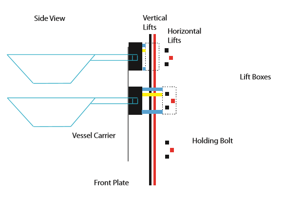
In this diagram, the lift boxes (drawn as dotted rectangles) are shown latching on to the vessel carriers using holding bolts.
The holding bolts can be withdrawn and relocked at will, allowing the vessel carriers to be transferred from one lift to another at points of intersection, and to allow horizontal lifts’ holding bolts to avoid colliding with vertical drive shafts.
Below is a rough schematic of the lift boxes.

The holding bolts are shown in blue.
The grippers (shown in solid black) hold on to the guide rails to stop the lift or onto the drive shaft(s) to propel the lift up or down.
We originally meant the system to have two counter-rotating drive shafts to allow the lift box to change direction very rapidly or stop against the drive rail.
The yellow square represents the gear wheels that power the tools (for mixing, stirring, etc).
The blue square are the holding bolts and they latch onto the vessel carriers through matching slots as shown below.

We had designed a gearing mechanism to lock and unlock vessel handles using cams that transferred power from the drive shafts and gears to power the tools, but those detailed diagrams have been lost.
Feasibility
An industrial robotics startup in Bangalore who evaluated this design for feasibility pointed out some problems in the design:
- The vertical plane of operation of the robot. They pointed out that lifting heavy vessels was going to require a lot of power, and would run into other problems like friction, and that it is always much easier to operate in the horizontal plane. They asked us to study food processor designs and come up with ways to transfer Indian food ingredients between vessels in the horizontal plane.
- Friction in many of the components could prove difficult to overcome, for instance in the vessel holder. The weight of the vessel and its ingredients might end up locking the split ring system and preventing it from turning, or it might end up jamming the holding shafts connecting the vessel holder and the lift.
So, it appears that a number of mechanical problems need to be solved before such a product could become a reality.

Hey there,
O have over come the physical challenge from a Mechanical point of view.
Cheers,
+Vinu